Advantages
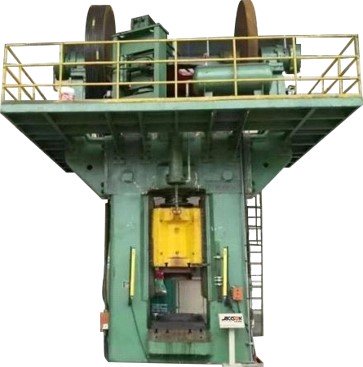
◎ Frame: The frame of the J54-4000 40000KN double disc friction press requires sufficient strength and rigidity. A
combined prestressed frame structure is adopted. There are positioning rings between the base, left and right
columns, and beams for positioning, and four pull rods are electrically heated and pre-tightened to form a closed
frame. Left and right support arms are installed at both ends of the upper part, which is convenient for installing
the transmission device.
◎ Transmission control system: The transmission is driven by double motors. There are two control cylinders
installed at both ends of the transmission shaft, through which the air is fed into the cylinders to push the piston to move left and right, so that the left and right friction discs are alternately pressed against the flywheel, so that
the flywheel drives the slider to move up and down, and the forging is completed, blow.
◎ Flywheel: The press adopts an overloaded slipping flywheel. When overloaded, there will be relative sliding
between the wheel body and the wheel rim to play a role of safety insurance.
◎ The body of the slider is made of high-quality cast steel. The lower end of the screw in the slider is equipped
with a nut. After the nut is tightened, a round pin is driven in to prevent loosening and falling out. The slider guide
adopts a long X-shaped guide rail, which improves the guiding accuracy and enhances the anti eccentric load
capacity of the product. The gap between the slider and the rack guide rail can be adjusted by means of
adjusting the inclined iron.
◎ Protection platform: This machine is equipped with a safety protection platform, which is the installation basis
of the braking device. It is welded by channel steel and angle steel. There is also a rat cage ladder for the upper
and lower platforms. It is convenient for the installation and maintenance of transmission control.
◎ Braking system: The braking consists of two identical sets of braking devices, which is symmetrically installed
on the platform. The upper part is tensioned by a tie rod, and the lower part is fixed on the platform by screws.
There are set screws on the platform to prevent the base from moving. When braking, the piston rod chamber of
the cylinder is exhausted. When the rodless chamber is inhaled, under the joint action of spring force and
compressed air, the piston rod pushes the brake plate through the shaft to press the outer edge of the flywheel,
so as to achieve the purpose of braking.
◎ Balance cylinder: The slider balance device is composed of two balance cylinders, which is symmetrically
distributed on the front and back of the machine beam, and are used to balance part of the weight of the motion
system, avoiding the sudden drop of the slider, making the slider move smoothly when it goes down, and is
conducive to Slider return.
◎ Ejection: Pneumatic double ejector rod structure is adopted, the ejection force is 20kN, and the ejection stroke
is 200mm.
◎ Air pipeline system: The air pipeline system is compressed air, which is used to provide power to the
transmission control, brake opening and slider balance device. The pneumatic system is composed of an air
storage tank, a reversing valve, a pressure reducing valve, a lubricator, safety valve etc.
◎ Lubrication: The equipment adopts centralized automatic lubrication and decentralized manual lubrication. The
four guide rails and the screw pairs of the main lubrication points use an electric pump and an automatic oil
separator to automatically inject lubricating oil for lubrication. The cylinder is lubricated by automatic oil spraying
with a lubricator installed in the air pipeline, and all other places that need to be lubricated are lubricated with oil
guns or grease cups.
◎ Foundation: The buyer invites a qualified civil engineering design institute according to the installation
foundation drawing provided by the seller and organizes the civil engineering construction after converting the
design into construction drawings according to the local soil conditions. The thickness of the foundation cement
pouring layer should be determined by the user after exploration according to the soil quality of the workshop.
The foundation should have a waterproof layer to prevent groundwater from seeping into the pit.
◎ Electric control system: It consists of a strong electric drive part and a PLC (OMRON) control part. The control
circuit is reasonable, the movement is reliable, and it is easy to use. The main motor adopts star-delta starting
mode, which reduces the impact of starting current.
Main Technical Parameters
|
Model
|
JSP-4000T
|
|
Function
|
Pressure Welding Process of Stainless Steel Composite Bottom Pan
|
|
Technology
|
Programmable Control System
|
|
Ton force
|
4000tons
|
|
Nominal force
|
40000kN
|
|
Slider stroke
|
800mm
|
|
Stroke times (theoretical calculated value)
|
9times/min
|
|
Minimum die height
|
800mm
|
|
Height of workbench pad
|
300mm
|
|
Working table size: left and right
|
1300mm
|
|
Front and rear
|
2350mm
|
|
Dimensions of the bottom of the slider
|
1110mm (left
and right)
|
|
Front and rear
|
2200mm
|
|
Ejection method
|
Pneumatic
|
|
Maximum ejection force of ejector
|
20kN
|
|
Maximum ejection stroke of ejector
|
200mm
|
|
Size
|
7961*5580*8960mm
|
|
Main motor
power
|
185×2kW
|
|
Peak power
|
385kW
|
|
Volitage
|
three-phase AC: 380V(±10%)50Hz
Three-phase four-wire single-phase AC: 220V(±10%)50Hz
|
|
Compressed air consumption
|
Consumes 1.2 cubic meters
per hit
|
|
Air supply
pipe diameter
|
≥ 40mm
|
|
Air supply
pressure
|
≥ 0.5MPa
|